
Devine Test Site: Lateral Heterogeneity in the Austin Chalk
Structural lateral heterogeneity is caused by detachment along the same normal faults that contribute to vertical heterogeneity. Fault dips are influenced by rock type, as discussed previously. Although a broad range of fault orientations may be expected, fault strikes subparallel, subperpendicular, and/or highly oblique to the regional east-northeast to west-northwest trend probably dominate (Figure 13). Marl smears (Figure 14) and rollover monoclines, features closely associated with normal faults, also cause lateral heterogeneity in chalk.
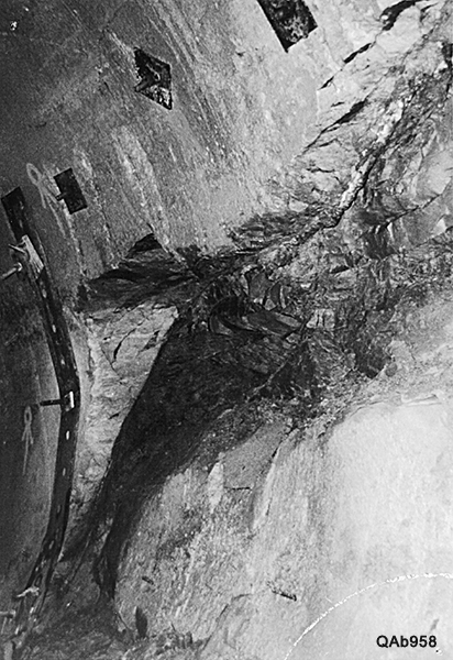
Figure 13. Marl smear associated with a normal fault (having 3-ft throw).
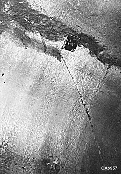
Figure 14. Joint located in upper Lower Austin Chalk, SSC tunnel. Joints terminate at chalk-marl bedding planes; however, joints may reappear in overlying chalk beds at the same location.
Where present in the subsurface, joints (extension fractures in which no vertical movement has occurred on either side of the fracture as shown in Figure 15) are probably subparallel to the regional structural trend and may additionally contribute to lateral heterogeneity. Joints are typically well developed in chalk but are absent in intervening marl beds (Friedman and Wiltschko, 1992: Nance and others, 1994). Joints may be open or mineral filled. Some joints are enlarged and contain water.
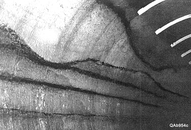
Figure 15. Small channel in lower Lower Austin Chalk, SSC tunnel. Maximum thickness of chalk channel fill is approximately 2 ft. Channel fill tapes laterally to about 1 ft. thick. Underlying chalk bed was eroded during channeling but is approximately 6 inches thick away from channel. Thin dark beds are marls.
Sedimentological lateral heterogeneity is caused by variations in bed thickness, depositional facies that are often associated with syndepositional erosional truncation of previously existing beds, and local mineralogical anomalies. A chalk layer may thicken locally into shallow erosional submarine channels (Figure 16). Larger channels ranging from 20 to 125 ft wide and as much as 8 ft deep may be filled with numerous thin cyclic chalk and marl layers.
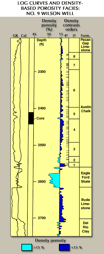
Figure 16. Initial definition of the suite of rock facies that comprise the interwell medium. This preliminary model uses the density log to depict the seismic propagation medium as a series of distinct rock facies that start as a coarse, first-order (1°) compaction trend and end as a detailed assemblage of thin, fourth-order (4°) beds.
Laminations in the channel fills also produce vertical heterogeneity. At the SSC site, channels are restricted to the lower Lower and Middle members of the Austin Chalk, are sinuous, and are generally oriented along dip (paleobasinward). Channels have been described from the Austin Chalk as far southwest as Langtry, Texas (Lock, 1984). Distances between channels in the SSC tunnels are greater than the channel widths, with 29 channels being identified in 6 mi of tunnel length. The boreholes at the DTS are aligned along a northwest to southeast dip (Figure 17); therefore, the probability of intercepting a channel having the same general orientation is reduced, although the typical sinuosity of a channel suggests some probability. Also, pyrite (Fe-sulfide) nodules up to 1 inch in diameter are widely disseminated in chalk and provide local variations in chalk composition.
Figure 17. Preliminary stratigraphy and facies model for the interwell P and S propagation medium.

