
The Water-Energy Nexus: Groundwater Studies
Brackish water resources and water treatment: studies that assess brackish water resources in Texas and disposal of industrial waste or flowback water.
CURRENT PROJECTS
Bridget Scanlon, PI: Assessment of Brackish Water Use for Hydraulic Fracturing: Case Study Eagle Ford Shale Play
J.-P. Nicot, PI: Evaluation of Water Use for Shale Gas in the Barnett Shale
J.-P. Nicot, PI: Nature of flowback: Water shale interactions at high temperature and pressure
REPORTS AND PUBLICATIONS
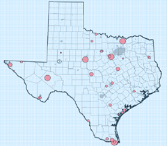
“A Desalination Database for Texas”
J.-P. Nicot
[download PDF]
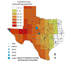
The goal of this work was to create a detailed central database ofdesalinization activities in Texas facilities.Over one hundred public water systems(PWS) engaged in desalinization were contacted, as well as several non-PWS facilities, mainly in the power and semiconductor industries. The results showed that the State of Texas in 2006 hosted about 38 PWS facilities with design capacities of at least 0.025 million gallons per day (MGD), whose cumulative design capacity was approximately 52 MGD. Approximately 50 additional PWS facilities with smaller design capacities hosted a further cumulative design capacity of less than 0.5 MGD. Hundreds of industrial facilities were believed to exist, with a cumulative design capacity of 60-100 MGD. Average production across the state was roughly half of design capacity. Across the state, both surface water and groundwater were used as feedwater, and the vast majority of facilities used reverse osmosis, although a small number used the electrodialysis reversal process.
“Brown County Brackish-Water Project: Ellenburger and Hickory Aquifers as a Public Water Supply”
J.-P. Nicot
[download PDF]
In this study, the Hickory and Ellenburger-San Saba aquifers were characterized in Brown County, Central Texas, to determine favorable locations for testing brackish water wells. These aquifers were selected because they represent the most extensive water resources in the county, even if the resources are not potable. The rocks in the area are organized simply, dipping radially away from the Llano Uplift, with the Hickory representing the first sediments deposited on the Precambrian-age basement. As the Hickory was never deeply buried, it has mostly conserved good permeability and flow quality. The Ellenburger, largely composed of Ordovician limestone, is a karstic aquifer in which high-permeability features tend to be concentrated around faults that may not be visible at the surface. The optimum well location for both aquifers appears to be near the southwest tip of the county, where the total dissolved solids concentration is relatively low, the formations are relatively thick, and the recharge zone is reasonably close to ground surface. Another location close to the city of Brownwood may be favorable due to the thickness of the Ellenburger, although total dissolved solids are likely to be much higher.
RPSEA Report on Paleozoic aquifers
[available on RPSEA website]
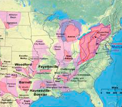
Abstract: During the fracture process, between 1 and 5 million gallons of water and sand is expended down hole into each extraction well to aide in the fracture. A portion of this water is recovered during the initial extraction of the gas. With proper management, recovered flowback water can represent a significant resource. Conversely, flowback water can represent a costly disposal problem. The nature of the chemistry and dynamics of recovered flowback water is of vital interest for effective environmental stewardship of a gas field. The objectives of this report are to better understand the chemical character of flowback water, its treatability, and long term sustainability issues associated with flowback water management. This project approaches flowback water management at shale gas sites from several distinct levels, from broad management issues, to testing of potential treatment technologies, to full-scale verification of a commercially available technology. Alternative water sources and treatment options are presented to reduce impact and provide potential cost savings. The scientific, engineering, and economic data presented in this report may be used to form the basis of rational engineering and sustainability management tools. This final report summarizes these findings, with data links to more detailed topical reports and (publication ready) papers available on the RPSEA website. Perhaps the broadest findings of this project are presented in the final task, Task 11; Preliminary Engineering Systems Analysis of Shale Gas Water Management, in which the water collection and salt generation at a hypothetical Marcellus gas play with 16 wells per field and 300 fields (4,800 wells) is projected for a period of 45 years into the future. In the early years of the play (its youth), the active fracture of new wells provides ample opportunity for the reuse of recovered flowback water within the play. As rates of fracturing of new wells and the refracturing of existing wells decline, the play enters middle age (first cross-over year) and the planned recovery volume exceeds the planned reuse volume. Segregation and pre-treatment of recovered water is at a premium. At some more future time, the rate of collection of produced water exceeds the rate of reuse (second cross-over) and the play is in old age. Water treatment and waste disposal become over-arching management issues. These findings put the remaining chapters into the perspective of these management needs. Chapter 4 investigates the chemistry of 19 flowback events in the Marcellus and 5 flowback events in the Barnett. These data suggest that the organic nature of the flowback water is very similar to produced water from oil wells. Heavy metals are not an issue. The major disposal issue appears to be inorganic scale formers. The initial 30% of the recovered water is much less salty than the final 70%, suggesting that one viable option for management of these waters is simple segregation (Chapter 5). Treatment of mid-range waters (TDS 10,000-60,000 mg/l) with advanced innovative reverse osmosis membrane technology is investigated in Chapters 9-10 and with enhanced electrodialysis in Chapter 8. The treatment of heavy brine (60,000-100,000 mg/l) with distillation (mechanical vapor recompression) is verified in a report on a full-scale facility in the Barnett (Chapter 7). Alternate water sources in the Barnett are examined in Chapter 6.
HARC Report on Eagle Ford
J.-P. Nicot
[contact author for copy of report]
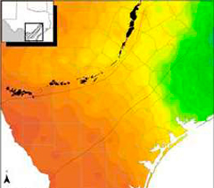
Executive Summary: This document presents an overview of mostly geological characteristics of formations in the footprint of the South Texas Eagle Ford (EF) Shale play with a focus on water. The ~25-county EF play has seen a dramatic development in the past few years and it keeps expanding to additional counties towards the north of the play. However, the EF area is not new to oil and gas exploration and production. At least 110,000 wells, not including the ~5000 EF wells (as of March 2013), has been drilled in the EF footprint during the past century, many of them still active. The EF shale is actually a source rock and has supplied oil and gas to reservoirs such as the Big Well and Pearsall fields and the very large Giddings field. Most of the EF lies in rural areas but several large cities (San Antonio, Laredo) are located at its edges. The document focuses on those two key aspects of hydraulic fracturing (HF): water use and water disposal. The South Texas location of the play with its scarcity of surface water resources exacerbates perceived conflicts with other water users. The large depth of the folded Paleozoic basement below the EF (>15,000 ft) allows for a thick sediment sequence of Jurassic and younger age. The EF shale is positioned towards the middle of the sequence (~4000 to 11,000 ft deep) leaving many formations between it and the ground surface, particularly the thick Midway Clay, and providing several horizons for disposal of fluids. EF's thickness varies from ~100 ft East of Austin to >500 ft at the Mexican border. The sedimentary sequence on top of the basement is initially carbonate-rich with platform carbonate formations such as the Edwards or Glenrose formations or the Austin Chalk , including the EF which is a carbonate mudrock. Toward the end of the Cretaceous the succession turned siliciclastic with alternating sandstones and claystones deposited in mostly fluvial and/or deltaic environments. Some of the sand-rich intervals of the succession compose the fresh water aquifers in the EF footprint such as the Carrizo aquifer and other aquifers of lesser water quality such as the Wilcox and Yegua-Jackson aquifers. Shallow subsurface water tends to be brackish outside of the outcrop area and of the Carrizo aquifer. Water use was ~24 thousand acre-feet (AF) in the EF play in 2011. In the same year, the top HF users in the EF consisted of Webb (4.6 kAF), Karnes (3.9 kAF), Dimmit (3.7 kAF), and La Salle (2.9 kAF) counties. Although overall water use has increased, water use per well has decreased. The change is related to the switch by most operating companies from the gas to oil and condensate windows and the use of gelled rather than slick-water HF jobs. Currently operators recycle very little of the flowback / produced water but use brackish water (likely in the vicinity of 20% of total water use). One reason why recycling is minor to negligible is that flowback volumes are far from providing enough water for a subsequent HF operation, especially at early times. The median well produces ~25% of the injected volume after 6 months and ~40% and plateauing after 1 year. Flowback / produced water is actually disposed of in injection wells. Approximately 2500 Class II injection wells were active at least part of one year during the 2008-2012 period. Many are related to waterflood operations and not to disposal. Preferred horizons for disposal are the formations of the Navarro-Taylor Groups in the Maverick Basin, a multi-county area next to the Mexican border as well as the Wilcox and Edwards formations.
“Disposal of brackish water concentrate into depleted oil and gas fields: a Texas study”
J.-P. Nicot
[download PDF]
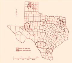
The goal of this study was to evaluate the technical aspects of disposing of concentrate from brackish water desalination plants in Texas into underpressured, depleted oil and gas fields. Six potential injection areas from across the state were selected for detailed analysis, all of which were characterized by a projected shortage of freshwater, abundant brackish groundwater, depleted oil and gas fields, and shallow injection wells. The oil and gas industry in Texas already has much experience injecting coproduced water back into hydrocarbon producing rock formations as part of pressure maintenance operations. The results of numerical modeling with SOMINEQ indicate that introducing desalination plant concentrate and subsequently mixing it with formation water should not present any technical problems outside those already commonly encountered in subsurface injections. Due to the abundance of depleted oil and gas fields in the state, this method of disposal is highly feasible and may be economically advantageous.
“Please Pass the Salt: Using Oil Fields for the Disposal of Concentrate from Desalination Plants”
Robert E. Mace, J.-P. Nicot
[download PDF]
This study was designed to evaluate the technical aspects of disposal of concentrate from brackish water desalination plants into depleted Texas oil and gas fields. The study addresses the concerns of precipitate formation and clay mobilization when concentrate is mixed with formation water, both of which may effectively plug a reservoir. The study also evaluates injectivity (the rate at which a reservoir may physically accept injected fluids) in six distinct areas of Texas as well as the potential for injected fluid to migrate to shallower freshwater aquifers. The study concludes that the risk of freshwater aquifer contamination is minimal to non-existent, and that following simple chemical treatment of desalination plant concentrate, injection into depleted oil and gas fields should not present any problems outside the range already faced by industry, while injecting coproduced brackish water back into hydrocarbon producing formations (a common and long held practice). The study recommends a change to governmental policy such that permits for injecting desalination plant concentrate may be more quickly and economically obtained.
“Self-sealing evaporation ponds for small inland desalination facilities and containment equivalence concepts in Texas”
J.-P. Nicot
[download PDF]
Evaporation ponds are a low-maintenance option for disposing of desalination concentrate, but cost may become an issue in the construction of pond liners. Currently approved pond liners include a three foot layer of in situ or compacted clay (with a hydraulic conductivity <10-7 cm/s) or a 30 mil geomembrane liner. An alternative liner may also be used if it can be demonstrated to achieve and maintain equivalent containment capabilities. The goal of this paper was to assess precipitation of the clay-like mineral sepiolite as a mechanism to either seal a geomembrane with defects or to create a effective lining across an entire pond bottom, removing the need for other linings. Results indicate that although sepiolite precipitation may effectively plug defects in geomembranes under assumed evaporation pond parameters, it is unlikely to meet legal standards as a self-sealing mechanism in the absence of other liners. Nonetheless, self-sealing sepiolite deposition may provide an additional useful barrier to groundwater contamination in sensitive environments, such as those with shallow unconfined aquifers.
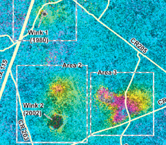
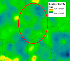
"Assessing collapse risk in evaporite sinkhole-prone areas using microgravimetry and radar interferometry: Journal of Environmental and Engineering Geophysics, v. 17, no. 2, p. 75-87."
Jeff Paine
[ download PDF]
Evaporation ponds are a low-maintenance option for disposing of desalination concentrate. Substantial savings can be achieved in Texas if exemptions are granted in the construction of pond liners. Currently approved liners include a ~0.9-m-thick layer of in situ or compacted clay (with hydraulic conductivity <10!7 cm/s) or a geomembrane liner >30 mil (0.075 cm). An alternative liner may also be used if it can be demonstrated to achieve and maintain equivalent containment capabilities with the preapproved liners. We examine (1) the possibility of incorporating a lowpermeability layer into the pond-liner system as a liner component or possibly as the liner itself as the pond water starts precipitating minerals, sealing any liner defect, and (2) the ability of the newlyformed minerals to, at minimum, plug liner defects. Assessment of previous laboratory experiments suggests that precipitation of a specific claylike mineral (sepiolite) could have many advantages. From geochemical calculations for assumed evaporation pond parameters, after 5 years of operation, an average precipitate thickness (mostly calcite and gypsum) is approximately 0.38 cm, containing about 7% sepiolite. Our analysis suggests that the precipitant, even with a conductivity >1× 10!7 cm/s, could efficiently plug defects of the geomembrane, allowing a thinner geomembrane to be used. On the other hand, the modest thickness of precipitant suggests that, to achieve equivalent containment, the precipitated material needs to have a conductivity n1×10!7 cm/s to impart the required properties to a scaled-down liner and to be successfully substituted in part or all of the clay liner. However, even if legal requirements are not fully met, self-sealing deposition could be advantageous in settings where an additional defense-in-depth layer is needed, such as areas with an underlying unconfined aquifer sensitive to contamination. In both cases (plugging defects or developing a blanket-like liner), cost remains an issue.
"Characterizing oil field salinization using airborne, surface, and borehole geophysics: an example from the upper Colorado River Basin, Texas"
Jeffrey Paine
[download PDF]
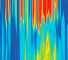
Multidisciplinary investigations of natural and oil field salinization along the upper Colorado River, Texas, present an opportunity to integrate results from a stream-axis airborne geophysical survey,ground and borehole geophysical surveys, and well drilling and sampling. Airborne electromagnetic (EM) induction measurements along 437 km (272 mi) of river and tributary stream axes identified discrete salinized streambed segments, including several near oil fields. Identification of these salinized streambed segments allowed more intensive and invasive investigations to be focused on the most significant near-river sources of salinity. One of these streambed segments lies adjacent to an oil field, where production began in the 1950s before discharge of coproduced brine into surface pits was prohibited in Texas. Monitor wells drilled after the airborne survey verified groundwater salinization in the oil field but did not adequately delineate salinization nor identify specific salinity source areas. Subsequent ground and borehole geophysical surveys complemented airborne EM induction and well data by establishing lateral and vertical salinization bounds in the oil field, discovering possible salinity source areas, and determining optimal locations for additional wells.
"Determining salinization extent, identifying salinity sources, and estimating chloride mass using surface, borehole, and airborne electromagnetic induction methods"
Jeffrey Paine
[download PDF]
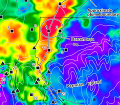
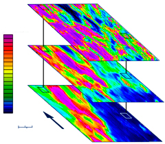
Using an example from an oil field in the semiarid Red River basin in Texas, we show that electromagnetic (EM) methods are useful in locating salinized soil and water, determining salinization extent, identifying likely salinity sources, and estimating the total mass of chloride within a saline-water plume. Each of these aspects assists in managing salinization and assessing its impact. We used ground EM instruments to establish salinization boundaries and determine the range of electrical conductivity, airborne measurements to locate potential sources and quantify the lateral extent and intensity of salinization, and borehole measurements and time domain EM soundings to determine salinization depth and relate ground conductivity to chloride content. We estimated infiltration volume and total chloride mass in the plume from EM data and an empirical, site-specific chloride:conductivity ratio established from well data. Because the measured conductivity of water strongly correlates with total dissolved solids concentration, mass estimation could be extended to any ionic constituent that covaries linearly with total dissolved solids concentration. EM methods owe their success to the large increase in electrical conductivity that occurs where highly conductive, saline water infiltrates geologic materials having naturally low conductivities.
"Identifying oil-field salinity sources with airborne and ground-based geophysics: a West Texas example"
Jeffrey Paine
[download PDF]
In this study, we evaluate the use of airborne and ground-based geophysical methods to locate near-surface saline water and discern its source in a test area where salinization arises from natural sources, oilfield activities, and agricultural practices. An airborne electro m a g n e t i c and magnetometer survey of a 91 km2 study area near Hatchel in Runnels County, Texas, defined the geophysical signature of salinized areas that have an oil-field source. The e l e c t romagnetic survey was designed to locate conductive ground associated with the presence of saline water. The magnetometer survey was designed to locate magnetic anomalies caused by well casings. Airborne geophysical signatures that might indicate a leaking well included conductivity anomalies at one or more of the electromagnetic exploration depths and either an associated magnetic anomaly or a known well location. Ground investigations focused on sites identified from the airborne survey. These included detailed geophysical surveys of sites and chemical analysis of soil and water samples. Because ground conductivity is not simply a function of p o re fluid chemistry but is also affected by soil type, rock type, and moisture content, these factors were considered. We then interpreted the most likely cause of the conductivity anomaly.

