
Instantaneous Amplitude
An illustration of the calculation of the instantaneous amplitude associated with a complex seismic trace is shown in Figures 3 and 4. A portion of a seismic trace is shown at the bottom of Figure 3, and the complex seismic trace corresponding to that trace is plotted at the top. The complex trace consists of a real part (the solid line), which is the same as the seismic trace at the bottom, and an imaginary part (the dashed line), which is the Hilbert transform of the real part. If the real part is x (t) and the imaginary part is y (t), then an amplitude quantity a (t) can be calculated at every data point, as will be shown in the following animation.
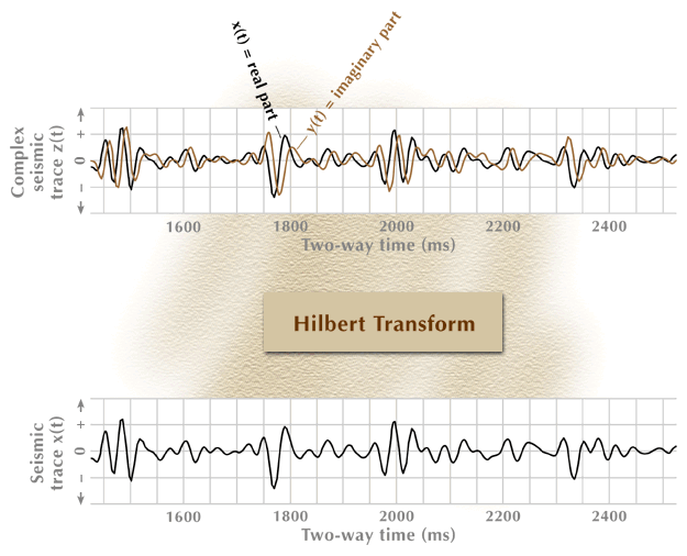
Figure 3. Construction of a complex seismic trace.
The animation sequence starts with the input data for the process (bottom), proceeds through an action step (center box), and then produces the required output function (top). Only three data points are processed through the action-step box.
The conversion of this complex trace into an instantaneous-amplitude function is described in Figure 4, where the amplitude function is plotted as an oscillating envelope enclosing the real and imaginary parts of the complex trace. The instantaneous amplitude is a positive definite function, meaning that its numerical value is always a positive number. It is plotted as both a positive and a negative function to emphasize the concept that it is the envelope of both the real and imaginary parts of the complex trace.
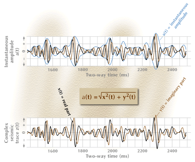
Figure 4. The instantaneous-amplitude function calculated from a complex seismic trace.
The animation sequence starts with the input data for the process (bottom), proceeds through an action step (center box), and then produces the required output function (top). Only three data points are processed through the action-step box.
![]()
 |
 |
| ©1999 AGI |