
The mathematical construction of a typical complex seismic trace by this double transform procedure is illustrated in Figure 4.
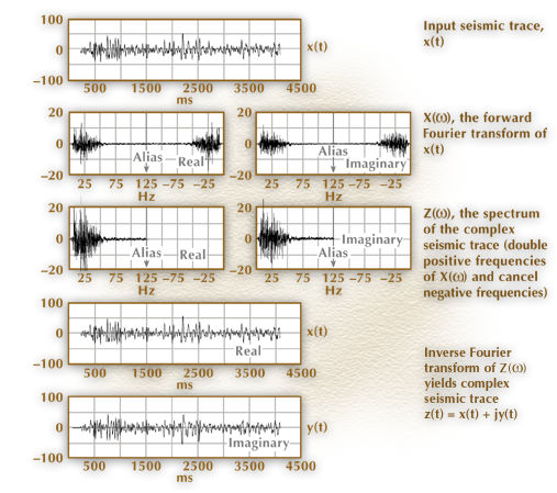
Figure 4. One computational scheme for calculating a complex seismic trace via forward and inverse Fourier transforms.
The figure shows that the frequency domain version of the analytic signal (line C) is obtained by doubling the Fourier transform of the real seismic trace (line B) for all positive frequencies, zeroing the function for all negative frequencies, and leaving the function unchanged at the zero and alias frequency values, which is what Equation 6 demands. The real and imaginary parts of the Fourier transform in lines B and C are shown just as they are calculated by the Fast Fourier transform algorithm with the negative frequencies occurring in the second half (right side) of the vector. The real part of the complex trace (line D) obtained from the inverse Fourier transform of the spectrum in line C can be seen to be identical to the input seismic trace shown in line A.
![]()
 |
 |
| ©1999 AGI |