 |
 |
| ©2000 AGI |

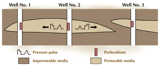
A diagram of a simple pressure interference test is shown in Figure 6 below. Well 2 is the pressure input well. Wells 1 and 3 are pressure observation wells. The idea is to inject a known pressure pulse into the perforated zone of the input well and then record the pressure reaction in the observation wells.

Figure 6. Pressure interference test.
In this example, the pulse should propagate to well 1, but the impermeable barrier between wells 2 and 3 should prevent the pulse from being transferred to well 3. By interpreting the pressure response (or lack of response), reservoir engineers can conclude that wells 1 and 2 penetrate a common compartment, but well 3 is in a separate compartment.